Knock sensor failure can trigger poor performance, check engine lights, and even engine damage if ignored. As a master technician, I’ve seen hundreds of misdiagnosed cases—often from overlooking simple wiring issues or installation errors. This guide cuts through the noise and gives you the practical knowledge to diagnose and fix knock sensor problems correctly the first time.
Electrical System Failures
Most “failed” sensors aren’t the problem—the wiring is. Before buying a new part, verify the circuit. These sensors output tiny voltage signals (often under 1V), so even minor electrical issues can corrupt readings.
Wiring Harness Damage and Shielding Issues
The harness runs near hot exhaust manifolds and vibrating engine parts, making it prone to wear. Damage here mimics internal sensor failure.
- Abrasion from engine vibration or contact with sharp edges—common near exhaust manifolds or broken harness clips.
- Rodent damage—especially in stored vehicles. Inspect under insulation with a bright light.
- Heat degradation—insulation becomes brittle and cracks, exposing wires to shorts.
- Shielding compromise—modern knock sensors use coaxial cables to reject electromagnetic interference (EMI). If the shield is pinched or grounded improperly, ignition noise or alternator ripple can fake a knock signal.
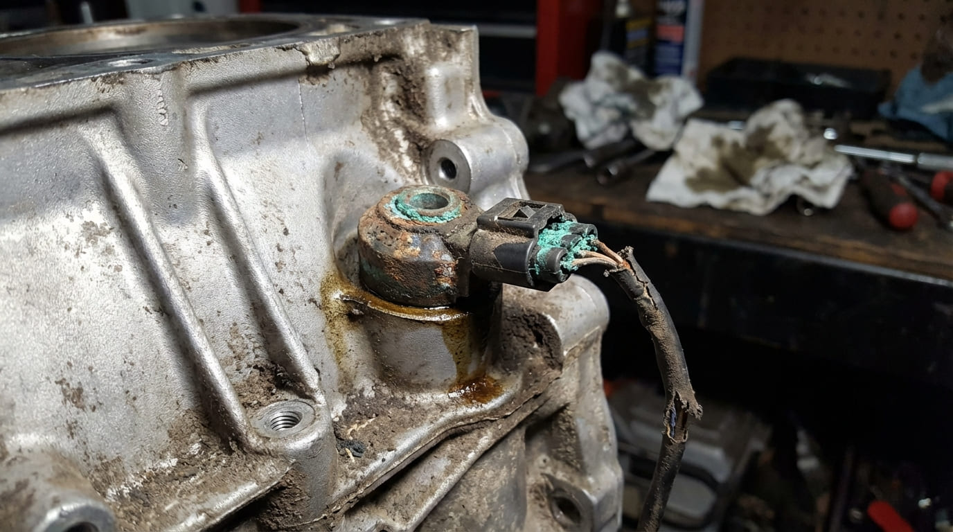
- Connector corrosion or pin fretting—moisture and thermal cycling cause oxidation, increasing resistance.
How to check: Use a multimeter to test for continuity and shorts. For shielding, measure resistance between the shield (usually the outer braid) and ground—should be 0Ω at the ECU end only. On an oscilloscope, look for high-frequency noise unrelated to engine RPM—this often points to EMI, not sensor failure.
In my shop, we always inspect the harness from the sensor to the ECU. I’ve cleared P0328 codes just by rerouting a pinched shield away from an ignition coil.
Ground Circuit Integrity Loss
A poor ground ruins signal accuracy. The sensor needs a clean return path to the PCM. Corrosion on engine ground straps or loose mounting points can mimic a dead sensor.
How to check: Perform a voltage drop test. With the engine running, measure between the sensor ground wire and battery negative. Anything over 0.1V indicates a bad ground. Clean all related grounding points with a wire brush and retest.
Mechanical and Environmental Damage
Mounted directly on the engine block, knock sensors endure extreme heat, vibration, and chemical exposure. This environment leads to predictable failure patterns.
Vibration Fatigue and Thermal Cycling
High-performance engines or high-mileage vehicles subject the sensor to constant stress. The piezoelectric crystal inside can develop microfractures, and solder joints can crack from thermal expansion.
How to check: Tap the engine block near the sensor with a metal tool while monitoring live data or an oscilloscope. A healthy sensor should show a clear spike. No response? Either the sensor is dead or the circuit is open.
Chemical Contamination and Physical Impact
Oil, coolant, or dirt leaking into the mounting area can degrade internal seals. Even a small dent from a wrench can alter the sensor’s resonant frequency or crush the internal element.
How to check: Remove the sensor and inspect the base. Look for white crust (corrosion), discoloration, or oil residue. If the housing is dented or cracked, replace it.
I once diagnosed a recurring P0327 on a V8—turned out a leaking rear main seal had soaked the sensor for months. Fix the leak first, or the new sensor will fail too.
Internal Sensor Failure
Even with perfect conditions, sensors wear out. But true internal failure is less common than assumed.
Piezoelectric Element and Circuit Board Failure
The crystal generates voltage when vibrated. Over time, it can lose sensitivity. Some sensors still “tap test” but produce weak signals below ECU thresholds (e.g., 0.3V vs. 0.8V).
Newer sensors have built-in electronics. These are sealed units—no repair possible. If the board fails, replace the sensor.
Housing Seal Failure
A compromised seal lets in moisture, leading to internal corrosion. This often causes intermittent faults that come and go with weather.
How to check: Inspect the sensor bore and threads during removal. If you see moisture or corrosion, clean the bore with a thread chaser and dry thoroughly before installing a new sensor.
Improper Installation: A Leading Cause of Repeat Failures
Many “failed” sensors were never bad—they were installed wrong. This is especially common with DIY repairs.
Torque and Mounting Surface Errors
The sensor must make solid metal-to-metal contact with the block. Any gap or contamination dampens vibrations.
- Overtorquing (e.g., >25 Nm on an M8 bolt) can crush the internal crystal.
- Undertorquing prevents proper acoustic coupling.
- Paint, old sealant, or corrosion on the mounting surface blocks vibration transfer.
How to check: Clean the bore with a small wire brush or bore cleaning tool. Use a thread chaser on the block threads. Always torque to spec—never “snug it down.”
In my shop, we use a calibrated torque wrench on every knock sensor. I’ve seen mechanics crack housings just by using a breaker bar.
Is It the Sensor—or Is the Engine Actually Knocking?
A P0325 doesn’t mean the sensor failed. It could be detecting real knock from carbon buildup, incorrect timing, or lean air/fuel ratios.
How to check: Use a mechanic’s stethoscope or chassis ear to listen for actual knocking under load. Compare with live data from a scan tool. If the sensor shows activity but you hear nothing, the circuit may be noisy. If you hear knock but the sensor is flat, the sensor or wiring is likely faulty.
Diagnostic Guide: Symptoms, Causes, and First Steps
| Symptom | Most Likely Cause | Less Common But Possible | Diagnostic First Step |
|---|---|---|---|
| P0327 (Low Input) | Open circuit in harness or failed sensor element | Undertorqued sensor, contaminated mounting surface | Check continuity and torque spec |
| P0328 (High Input) | Short to voltage or ground in wiring | Failed internal electronics, ECU issue | Inspect harness near exhaust and connector |
| P0329 (Intermittent) | Loose connector, pin fretting | Cracked solder joint, thermal cycling damage | Wiggle test with live data monitoring |
| No DTC but poor performance | Actual engine knock (carbon, timing, AFR) | Failing sensor not yet tripping code | Use stethoscope and live data under load |
Real-World Diagnostics: Lessons from the Shop
Situation: 2012 Ford F-150 with P0325 and limp mode. Owner replaced the sensor twice—code returned.
Diagnosis: Found melted harness insulation near the exhaust manifold. The shield was shorted to ground.
Lesson: Always inspect the entire harness. A new sensor won’t fix a wiring problem.
Situation: 2008 Honda Accord with P0327. No knock heard.
Diagnosis: Mounting hole clogged with old thread sealant. Cleaned and reinstalled with correct torque—problem solved.
Lesson: Acoustic coupling is critical. A clean, flat surface is non-negotiable.
Situation: 2015 GM V6 with intermittent P0329. Customer had a new sensor ready.
Diagnosis: Signal dropped when wiggling the connector at the firewall. Cracked housing allowed moisture in.
Lesson: Intermittent faults hide in connectors. Wiggle test under live data—it’s fast and revealing.
Best Practices: Do and Don’t
- ✅ Clean the mounting bore and threads before installation—use a wire brush and thread chaser.
- ✅ Torque to spec—use a calibrated torque wrench. Typical range: 20–25 Nm for M8 bolts.
- ✅ Inspect harness routing—keep it away from hot or moving parts.
- ⚠️ Don’t reuse torque-to-yield bolts—they lose clamping force after first use.
- ⚠️ Don’t use thread locker or sealants on the sensor body—they dampen vibration.
- ⚠️ Don’t skip ground inspections—clean and tighten engine ground straps when replacing the sensor.
Knock sensor issues are often misdiagnosed because the symptoms mimic other problems. Focus on the full system: wiring, ground, mounting, and actual engine condition. A new sensor costs $50–$150, but a misdiagnosis leads to repeat labor and frustration. Test the circuit, verify installation, and use live data—don’t guess. When in doubt, consult the factory service manual for torque specs, waveforms, and testing procedures specific to your vehicle.