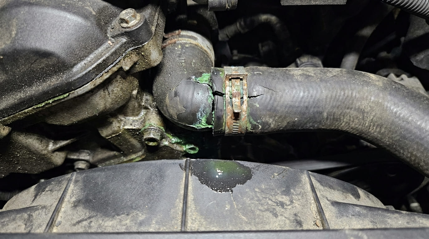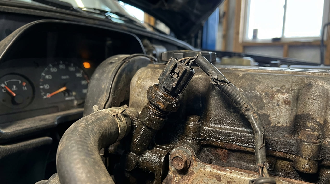
Over two decades in the bay, I’ve seen more than a few panic-stricken owners roll in with a temperature gauge stuck at cold or pegged at hot. The instinctive reaction? “Replace the thermostat” or “swap the coolant sensor.” But real diagnostics don’t start with parts—they start with systems. A non-functional gauge isn’t just a reading problem; it’s a signal chain issue, and in my experience, jumping to conclusions burns time and money. Let’s walk through a methodical, layered diagnosis that respects the complexity of modern vehicles.
Initial System Assessment
Before touching a single wire, confirm whether the engine is actually overheating—or if it’s just the gauge lying to you. I can’t count how many times I’ve seen perfectly healthy engines sidelined because someone trusted a faulty needle.
Verify Actual Engine Coolant Temperature
In my shop, we use a dual-verification method: OBD2 live data and an infrared thermometer. This cross-check catches sensor drift or wiring faults early.
- OBD2 scanner: Monitor the Engine Coolant Temperature (ECT) Parameter ID (PID) as the engine warms up.
- Infrared thermometer: Aim at the thermostat housing or upper radiator hose—avoid painted surfaces or reflective areas.
The two readings should align within 5°C (9°F) at operating temperature. A significant discrepancy usually points to a sensor or circuit fault—not necessarily engine trouble. If the ECT PID climbs normally but the gauge doesn’t move, the issue lies downstream of the sensor.
Check for Diagnostic Trouble Codes (DTCs)
Even if the check engine light isn’t on, scan for pending codes. Some ECT-related faults won’t illuminate the MIL but will store soft codes.
Key DTCs to watch for include:
- P0115 – Engine Coolant Temperature Circuit Malfunction
- P0116 – ECT Circuit Range/Performance
- P0117 – ECT Circuit Low Input
- P0118 – ECT Circuit High Input
- P0119 – ECT Circuit Intermittent
These codes don’t automatically mean the sensor is bad—just that the signal is out of expected range. Could be wiring, a poor ground, or even a failing PCM. Always clear codes after repair and retest under the same conditions.
Engine Coolant Temperature (ECT) Sensor Diagnosis
The ECT sensor is typically a Negative Temperature Coefficient (NTC) thermistor. As temperature increases, resistance drops. Most failures I see are either open circuits or drifted resistance values—not always a complete failure. Replacement sensors cost $15–$60; OEM units last longer but cost more.
Sensor Resistance Test (Cold Engine, Ignition OFF)
- Disconnect the sensor connector.
- Set a digital multimeter (DMM) to measure resistance (Ohms).
- Measure across the two terminals.
- Compare to the OEM resistance-vs-temperature chart.
At 20°C (68°F), many NTC sensors read between 2.5 and 3.5 kΩ—but this varies by manufacturer. Some Ford units run lower; certain European models higher. Always consult the service manual for the correct curve.
An open circuit (OL) or dead short (0 Ω) is a clear failure. But in my experience, gradual resistance drift—say, 4.8 kΩ at 20°C—is more common and often missed. That small error can throw off fuel trim and gauge readings.
In my shop, we always bench-test replacement sensors before install. I’ve seen brand-new units out of spec right out of the box—saves a comeback.
Sensor Voltage Output Test (Engine Running)
With the sensor connected, backprobe the signal and ground wires. Voltage should drop as the engine warms.
Typical behavior:
- Cold: 4.0–5.0V
- Hot: 0.5–1.5V
If voltage stays high, the PCM thinks the engine is cold—long fueling, poor idle. If it’s stuck low, the engine might overheat before the PCM reacts. But be careful: backprobing can damage terminals. I recommend using pin-saver probes or breakout harnesses when possible.
Wiring Harness Integrity Diagnosis
More than once, I’ve replaced a “bad” sensor only to find the real issue was a chafed wire in the harness rubbing against the exhaust manifold. Repairing a harness section costs $20 in materials but can save $300 in unnecessary parts. Always inspect routing near heat sources.
5-Volt Reference Voltage Check
With the ignition on and sensor disconnected, check for ~5.0V on the reference wire. No voltage? Could be an open in the harness or a failed internal regulator in the PCM. I’ve seen both. Use a DMM to check continuity back to the PCM if the voltage is missing.
Ground Circuit Resistance Check
Resistance from the sensor’s ground pin to a solid chassis point should be under 0.5 Ω. Higher? Look for corroded connectors or a loose ground strap near the engine block. Clean ground points with a wire brush and apply dielectric grease to prevent future corrosion.
Signal Wire Testing
With both ends disconnected, check continuity between the sensor and PCM. Less than 0.5 Ω is good. Then test for shorts:
- Signal to ground: Should be >10 kΩ
- Signal to battery positive: Should be >10 kΩ
A short to ground will pull the signal low, mimicking a hot engine. A short to power pegs the gauge high. These faults are often intermittent—jiggle the harness while monitoring with a scope to catch them.
In my shop, we always perform a wiggle test with the scanner live. If the ECT reading jumps while shaking the harness, you’ve found an intermittent break. Seal and repair with heat-shrink butt connectors—never electrical tape.
Instrument Cluster (IC) / Gauge Diagnosis
When the sensor and wiring check out, the problem likely sits in the cluster. But don’t yank it out just yet—run the self-test first. Replacing a cluster costs $200–$600 and often requires programming. Avoid this unless confirmed.
Cluster Self-Test
Many vehicles have a built-in gauge sweep routine. For example, hold the trip reset button and turn the ignition to ON. If the temp gauge doesn’t sweep, the stepper motor or internal PCB trace may be faulty. If it does, the gauge mechanism is likely functional—but that doesn’t rule out signal processing issues.
Signal Simulation (Advanced)
In the shop, I simulate sensor input using a variable resistor or signal generator. Disconnect the ECT sensor and feed a known signal into the harness. If the gauge still doesn’t move, the fault is in the cluster or the data path from PCM to cluster.
On CAN-bus vehicles, the PCM sends ECT data digitally. A failed CAN message due to ECU glitch or bus noise can silence the gauge even with a perfect sensor. Use a scanner that can monitor CAN communication status.
We once fixed a “dead” gauge on a BMW by reseating the PCM connector. Corrosion on the pins disrupted the CAN signal. A $5 contact cleaner and a few minutes saved a $500 cluster replacement.
Powertrain Control Module (PCM) Diagnosis
This is the last stop. If the sensor, wiring, and cluster all test good, and live data shows correct ECT input, but the gauge still doesn’t work—the PCM may not be sending the correct output.
In some cases, the PCM processes the ECT signal correctly for fuel and spark but fails to route it to the instrument cluster. An advanced scanner with bi-directional control can monitor both input and output streams. If input is good but output is missing or frozen, the internal logic or driver circuit is suspect.
PCM failures are rare, but they happen—especially after jump-start mistakes or water intrusion. Replacement usually requires programming with OEM-level tools. Refurbished units cost $150–$400; programming adds $100–$200. Consider repair services for high-end models.
Best Practices Checklist
- ✅ Recommended: Use an OBD2 scanner to verify actual ECT before condemning any component. Prevents misdiagnosis.
- ✅ Recommended: Clean sensor threads with a bottoming tap before installation. Debris can cause poor thermal contact or thread damage.
- ✅ Recommended: Check for pending DTCs, not just stored ones. Intermittent faults often show up here first.
- ⚠️ Avoid: Backprobing with sharp probes. Damaged terminals lead to corrosion and future opens.
- ⚠️ Avoid: Assuming a new sensor is good. I’ve bench-tested brand-new sensors out of spec.
- ⚠️ Avoid: Replacing the instrument cluster without simulating the input signal. Many “bad clusters” are actually upstream issues.
Diagnostic Decision Table
| Symptom | Most Likely Cause | Less Common But Possible | Diagnostic Priority |
|---|---|---|---|
| Gauge reads zero, ECT PID normal | Open in gauge signal circuit or cluster fault | PCM output driver failure, CAN communication loss | Check cluster self-test first |
| Gauge reads max, ECT PID normal | Short to ground in signal wire | Failed PCM pull-up resistor, cluster internal short | Test signal wire for shorts |
| ECT PID erratic, gauge follows | Loose connector, chafed harness | Failing sensor, poor ground | Inspect wiring, check ground resistance |
| Both gauge and PID stuck cold | Open circuit in sensor or harness | Faulty PCM reference voltage, failed sensor | Verify 5V reference first |
| Both gauge and PID stuck hot | Short to ground in sensor circuit | Failed sensor, coolant level low (thermal runaway) | Check sensor resistance, inspect harness |
Case Studies from the Bay
Situation: 2012 Chevrolet Silverado with gauge stuck at cold. No DTCs. Owner replaced thermostat twice.
Initial Assumption: Bad ECT sensor.
Discovery: Sensor resistance was out of spec. But after replacement, gauge still dead. OBD2 showed correct ECT PID. Cluster self-test failed—the gauge didn’t sweep.
Nuanced Lesson Learned: Just because the PCM reads the sensor doesn’t mean the signal reaches the cluster. The fault was a failed stepper motor in the instrument cluster, not the sensor or wiring.
Situation: 2008 Toyota Camry with intermittent high-temp gauge. No overheating, no DTCs.
Initial Assumption: Wiring chafe near exhaust.
Discovery: Wiring checked fine. IR thermometer matched OBD2 data. But when I monitored the signal with a scope, I saw voltage spikes every time the A/C compressor cycled.
Nuanced Lesson Learned: Electromagnetic interference from the compressor clutch was coupling into the ECT signal wire. A shielded repair section and rerouting solved it—no parts replaced.
Situation: 2015 Ford Fusion with gauge pegged hot. ECT PID read 140°C. Coolant level was fine.
Initial Assumption: Blown head gasket.
Discovery: Compression test normal. No exhaust in coolant. But resistance check showed ECT sensor at 50 Ω—way too low. Bench test confirmed it was faulty. No engine damage.
Nuanced Lesson Learned: A failed sensor can mimic catastrophic engine failure. Always validate with multiple data sources before disassembling.
Temperature gauge diagnostics require patience and layered testing. I’ve seen too many techs skip steps, replace parts, and still not fix the issue. The real skill isn’t in knowing what to replace—it’s in knowing what to test, and in what order. Always refer to the vehicle-specific service manual for exact specifications and procedures; what works for one model may not apply to another.