In my shop, I’ve seen more than a few engines come in with crank-no-start issues, only for the tech to replace the starter or fuel pump before checking something as fundamental as the camshaft position sensor. Over the years, I’ve learned that understanding the role of the CMP sensor—and how it interacts with other systems—is critical for efficient, accurate diagnosis. This isn’t just about replacing a part; it’s about understanding timing, synchronization, and the ECM’s decision-making process.
Core Function of the Camshaft Position Sensor
The camshaft position (CMP) sensor tells the engine control module (ECM) exactly where the camshaft is in its rotation. This allows the ECM to determine which cylinder is on the intake stroke and when to fire the fuel injector or spark plug. Without this signal, modern engines—especially those with sequential fuel injection—can’t run properly, if at all.
It works in tandem with the crankshaft position sensor (CKP). While the CKP tells the ECM engine speed and crankshaft position, the CMP confirms valve timing and cylinder position. Together, they enable precise fuel and spark delivery.
How to Check if the CMP Signal is Missing
Use a scan tool that reads live data:
- Monitor both CMP and CKP RPM readings during cranking—they should match and stabilize quickly.
- Look for a “Cam/Crank Correlation” PID. Most engines allow no more than 2–3 degrees of deviation. Larger offsets indicate sync issues.
- If the ECM shows “Not Synchronized” or “Sync Lost,” suspect CMP, CKP, or mechanical timing problems.
If no signal is present, proceed to electrical and mechanical checks.
Sensor Types and How They Work
Two main types exist: Hall Effect and Inductive. Knowing which your vehicle uses affects how you test it.
Hall Effect Sensor
Most common in vehicles after 2000. Provides a clean digital signal, reliable at all engine speeds.
- Requires power (5V or 12V), ground, and a signal wire.
- Outputs a square wave signal as a notched reluctor wheel passes through its magnetic field.
- More accurate and less prone to failure at low RPM than inductive sensors.
Inductive (Reluctance) Sensor
Older design, still found on some models. Self-powered but less reliable at cranking speed.
- No external power required—generates its own AC voltage.
- Produces an analog sine wave; signal strength depends on engine speed.
- Weak or no signal at cranking can cause no-starts, even if the sensor is functional.
Diagnostic Steps and Tools Needed
Before replacing the sensor, verify the real cause. Many “bad CMP” diagnoses are actually wiring, connector, or mechanical issues.
Step-by-Step Diagnostic Procedure
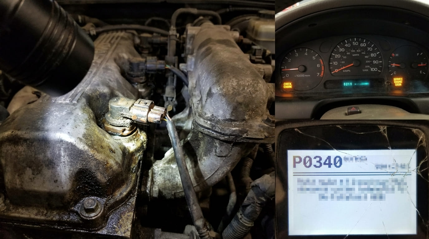
- Scan for codes and live data: Check for P0340–P0343 or OEM-specific codes. Monitor CMP signal activity.
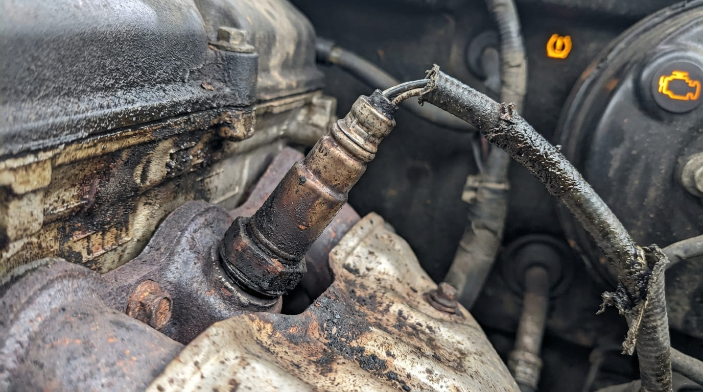
- Visual inspection: Look for damaged wiring, oil in the connector, or physical damage near the sensor.
- Check power and ground (Hall Effect only): With key on, test for proper voltage and ground at the connector.
- Test signal output: Use an oscilloscope or multimeter to confirm signal generation while cranking.
- Inspect the reluctor wheel: If no signal and electricals are good, remove covers to check for damaged or loose reluctor.
| Test | Expected Result | Notes |
|---|---|---|
| Power Supply (KOEO) | 5V or 12V (varies by OEM) | Always consult wiring diagram—some use ECM pull-up |
| Ground Circuit | < 5 ohms to chassis | Poor ground mimics sensor failure |
| Hall Effect Signal | Square wave, 0V to supply voltage | Backprobe—never pierce wires |
| Inductive Signal | AC sine wave, increases with RPM | No signal at rest—must crank engine |
| Resistance (Inductive Only) | 800–1200 ohms typical | Varies—check service manual |
Common Symptoms of a Failing CMP Sensor
A faulty CMP sensor disrupts engine timing control. Symptoms vary by system:
- Engine cranks but won’t start—especially in sequential fuel injection
- Extended cranking before start—ECM may need multiple revolutions to sync
- Intermittent stalling at idle or under load
- Rough idle and misfires—due to incorrect injector or spark timing
- Check Engine Light with CMP-related codes (P0340–P0343)
- Reduced fuel economy—ECM may run in open-loop mode
Note: Some engines default to batch fuel injection and run poorly. Others won’t start at all.
Repair vs. Replace: Cost and Viability
The CMP sensor itself typically costs $30–$120. Labor ranges from 0.5 to 1.5 hours depending on location. However, don’t replace it blindly.
Common pitfalls:
- Oil contamination in the connector—clean and seal with dielectric grease.
- Melted wiring near exhaust—repair harness, not just the sensor.
- Reluctor wheel damage—requires disassembly and possibly camshaft replacement.
Ask: Is the code intermittent? Did someone already replace the sensor with no fix? That suggests a deeper issue.
Situation: A 2012 Honda Accord came in with a crank-no-start and P0340. The owner had already replaced the CMP twice.
Discovery: After checking the signal with a scope, I found no waveform. Power and ground were good. Then I pulled the valve cover—turns out the reluctor wheel had detached from the camshaft due to a failed press fit.
Nuanced Lesson Learned: Just because the code points to the sensor doesn’t mean the sensor is the problem. Always verify signal generation at the source.
Situation: A Ford F-150 with intermittent stalling. P0341 stored, but not always present.
Discovery: The wiring harness near the exhaust manifold was melted. The insulation had broken down, causing a short when the engine got hot.
Nuanced Lesson Learned: Intermittent electrical faults often have physical causes. Heat, vibration, and oil exposure are relentless enemies of sensor circuits.
Situation: A Subaru with rough running and misfires. P0340 and P0016 (cam/crank correlation).
Discovery: The timing belt was jumped—just one tooth. The CMP and CKP signals were out of sync, but both sensors were functional.
Nuanced Lesson Learned: CMP-related codes can be symptoms of mechanical timing issues, not just electrical ones. Always consider the big picture.
Best Practices for Diagnosis and Replacement
- ✅ Recommended: Use a scan tool with live data before replacing any sensor—verify the signal is truly missing or erratic.
- ✅ Recommended: Clean sensor threads with a tap—oil or debris can affect air gap and signal.
- ✅ Recommended: Apply dielectric grease to the connector to prevent moisture and oil ingress.
- ⚠️ Avoid: Reusing torque-to-yield bolts on sensor brackets—they can lose clamping force and cause vibration damage.
- ⚠️ Avoid: Piercing wires during testing—backprobing is safer and prevents future corrosion.
- ⚠️ Avoid: Assuming the part store sensor is calibrated the same as OEM—some aftermarket units have different signal characteristics.
In my shop, we always test before we replace. A $100 sensor won’t fix a broken wire or jumped timing. Treat every code as a clue, not a verdict. With the right tools and methodical approach, you’ll save time, money, and frustration.